Phase VII: Split Power Distribution Bus Into Main And Essential Circuits
Given the completion of the previous phases, we now have our way to actively notify the pilot of any failure in the electrical system. So, if something does happen (and it will); what are we to do next?
When the light does come on, we have several options: If comfortable haven is close by and our battery is a known quantity, then perhaps no special action is needed other than to turn the alternator off to reduce its field circuit load on the battery. It would be wise at this time to dump unnecessary loads but a fairly relaxed activity to get on the ground is appropriate.
If the event is an alternator failure we must make the most of finite energy stored in the battery given the possibility that a desired location for landing could be some distance away. To do this we must have a reasonable idea of how much battery energy is available, how much equipment we consider to be critical to the completion of a safe flight, and how much energy each of these components use. Once we determine this information, we must act upon it.
Needless to say, trying to deal with an electrical failure is not the time to be doing our research. It's best to have determined this information ahead of time and have the decisions already made. Even better, why not bring all of the non-critical systems off-line with a simple flick of a switch?
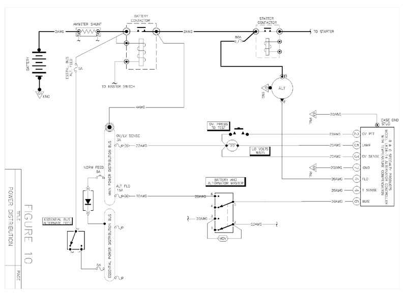
Figure 10 offers the concept of a power bus split into a Main Bus and an Essential Bus. The Main Bus is based on the original as-delivered power distribution bus, but with a twist: all of those components that we have pre-determined to be critical to the safe completion of our flight have been moved over the Essential Bus. The opposite end of the Essential Bus is tied directly to the battery's positive terminal through a manually controlled push-pull breaker.
A silicon diode having a forward current rating of 20 amps or more is used connect the two busses together and to provide automatic isolation of the power distribution from the essential bus during failed alternator operations. Without this automatic isolation, poor pilot technique during a perceived emergency could result in inadvertent overloading of Essential Bus Alternate Feed Path and leaving one totally in the dark!
Here's how the system works:
Our intrepid pilot is tooling along through the skies IFR. Suddenly, his "Low Voltage" warning light comes on, notifying him of a problem. He looks at the ammeter and notices that it is hard over into the discharge side of the gauge; if the overvoltage breaker has not tripped he can reasonably conclude that his alternator, or one of the main feed wires, has failed.
Having come to this conclusion, our pilot reached over and closes the Essential Bus Alternate Feed Breaker, allowing direct battery power to the Essential Bus. Then, in order to isolate the remainder of the electrical system from using up precious battery energy, our pilot opens the Battery Master and Alternator Switches.
In just TWO SIMPLE MOVES our pilot has completely isolated his electrical usage to only those items that are critical to safe completion of the flight. No muss, no fuss. No need to think, no opportunity to screw up.
Note that by taking a battery contactor off-line we've reduced the load on the battery by several hundred milliamps (equal to several solid state NAV receivers!) Setting up the system in this manner isolates the essential bus and provides a direct path to the battery
The idea of making a solid connection between main bus and essential bus via diode makes sense. Any time the main bus is hot, the essential bus is too. The main bus can be shut down at any time to conserve finite battery energy with zero risk of backfeeding from the essential bus and blowing the alternate feed protection.
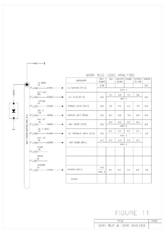
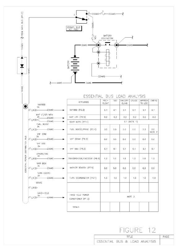
As part of our whole electrical system design, we will do a detailed analysis of exactly which components used exactly how much battery energy, and which we're going to need. We want to be able to make educated decisions as to which items are needed, and how much energy they will use. Figure 11 and Figure 12 offer example analysis of which components should be considered for each bus, and the average consumption that each component is expected to use.
Armed with all of this pre-determined information, along with a supplemental voltmeter measuring the essential bus to keeps tabs on the available battery energy remaining, our pilot can now make a reasonable and safe command decision on whether our flight can continue to its intended destination.
Which, after all, was the goal of the flight in the first place.
Once our pilot arrives in the Terminal Area with plenty of electrical energy to spare, he can flip on the Master Switch, turn on all lights a-blazin', land and have his system problems checked out.
A simple, yet elegant, solution.