Phase IV: Install Solid-State Voltage Regulator with Crowbar Overvoltage Protection
Alternator charging systems are susceptible to overvoltage due to a malfunction of the voltage regulator. The necessity for reliable overvoltage protection in airplanes is not debatable.
During 1996 I had been experiencing failures of various electrical components in the Tiger, mostly in avionics. Since the failures were in new, warranted radios, I had attributed their demise to "infant mortality" of new parts. However, as the same radios failed again I contacted the manufacturer and queried as to the most likely reasons for these failures. Their answer was overvoltage, voltage "spikes," or lightning strikes.
Since I was reasonably certain that I had not been struck by lightning recently (I think I would have remembered that) I had the aircraft system voltage measured. I was quite surprised to find that the system voltage was at 15.6 volts! Even more sobering was the fact that it had likely been this way for the previous two years I had owned the airplane, and yet the factory overvoltage protection had not tripped.
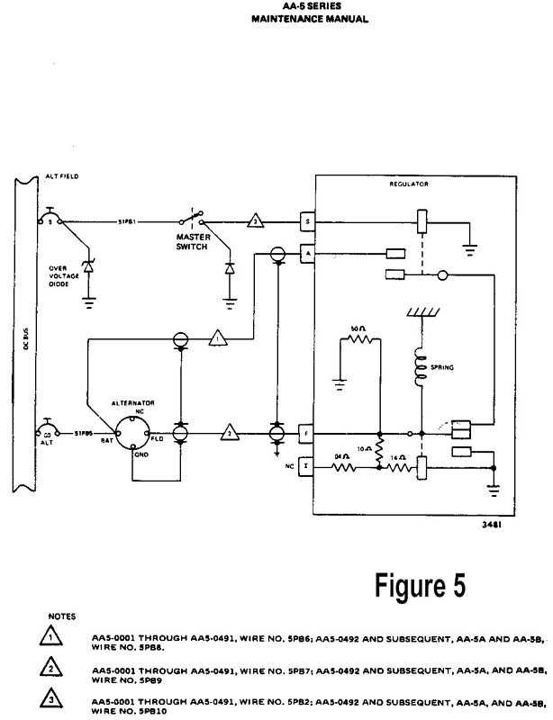
The 1977 Tiger's overvoltage protection (Figure 5) consists of an "avalanche" overvoltage diode that is shunted across the load side of the alternator field circuit to ground. This diode will withstand the aircraft's normal bus voltage, but is supposed to break down under excessive voltage and short the alternator field circuit to ground. This will "crowbar" the alternator field circuit breaker to open, disabling the alternator.
Unfortunately, reactivation of the field circuit breaker cannot be accomplished until the electrical failure is corrected, AND the avalanche diode is replaced. This diode is expensive and is in a very difficult area to access. Needless to say, field repair in outlying areas could not be done expeditiously.
However, the simplicity and reliability of crowbar overvoltage protection is difficult to beat.
When a voltage regulator fails, the system manifests the failure in several ways. First, it can fail passive; the system simply quits. Alternatively, the system may become unstable; e.g. the regulated voltage setting may oscillate or drift depending on the nature of the failure. Lastly, the system may go into voltage "runaway". The latter condition is usually brought about by failure of the major current carrying device in the regulator that is supposed to modulate alternator field current. Instead, full bus voltage is applied to the alternator causing bus voltage to climb rapidly to levels hazardous to electrical components in the airplane.
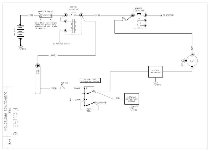
The task of overvoltage protection is to sense an impending runaway and bring the alternator system under control before things get out of hand. The circuit shown in Figure 6 shows how the crowbar OV Module is connected from the alternator field supply to ground. The module is designed to throw a dead short on the supply lead when the bus voltage rises above the OV trip point for the module. This action causes the alternator field supply breaker to open in milliseconds thus depriving the alternator of field excitation voltage. The whole event is over before it gets started, and field circuit breaker is not asked to do anything that it was not designed to do.
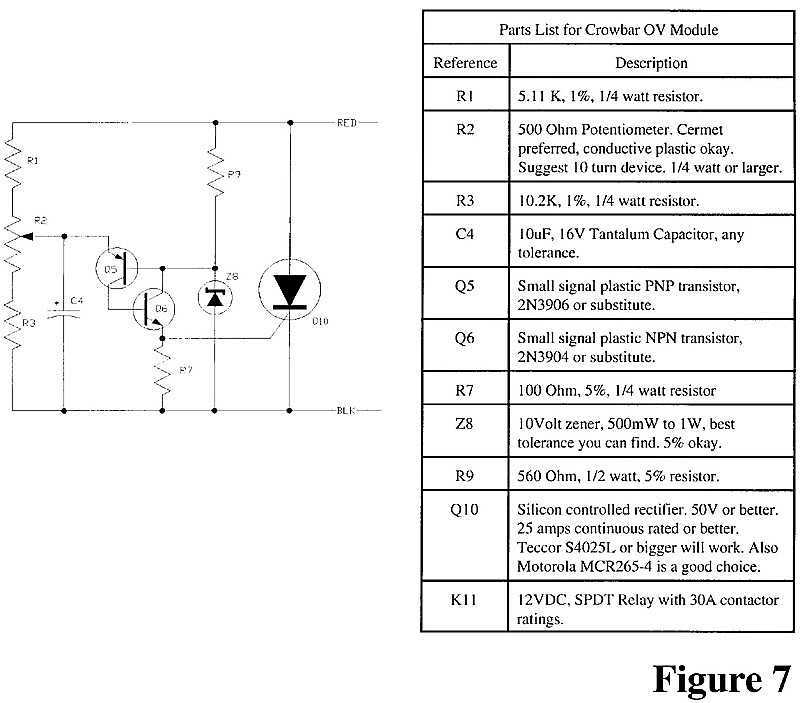
Figure 7 shows a basic schematic for a crowbar OV protection module. The workhorse in this circuit is a silicon controlled rectifier (SCR - Q10). The part is rated for 25 amps or more continuous duty and several hundreds of amps for the milliseconds required to open a circuit breaker. The array of resistors and the potentiometer (R1, R2 and R3) are used to scale down a nominal bus voltage to a level appropriate to the voltage sense and trigger components. A capacitor (C4) from the arm of the pot forms a time delay network of some tens of milliseconds to prevent normal perturbations of bus voltage from causing nuisance trips of the OV protection system. Transistors (Q5 and Q6) along with resistor (R7) and zener (Z8) take on the sensing and trigger duties for OV Module operation. The NPN-PNP pair of transistors form a quasi 4-layer trigger device. When Q5 is driven into conduction by elevating its emitter lead more positive than zener voltage, it applies base drive to transistor Q6 turning it on also. Q6 is coupled back to the base of Q5 in positive feedback. The result is a snap action switch that dumps the charge on capacitor C4 into the gate of the silicon controlled rectifier causing it to go into conduction. Heavy current flowing through the triggered SCR produces the fault current needed to "crowbar" the alternator field breaker open.
Therefore, when an overvoltage condition is detected, the circuit breaker controlling the alternator will be opened bringing the failed system under control in a few tens of milliseconds. The end result is identical to the Tiger's factory overvoltage "crowbar" protection, but it does not destroy components during the process as the factory system does.
However, this system is not complete without active notification of alternator failure. It's important that the pilot be able to shed loads and make alternative plans as soon as possible in response to an alternator failure or over voltage event. Installation of visual notification of alternator failure should be incorporated as a minimum electrical safety device in any aircraft. Unfortunately, the Grumman Tiger was certified without this safety feature.
The combination of all three aspects (voltage regulation, overvoltage failure protection, and active notification of system failure) is incorporated into a currently available product, the LR3B voltage regulator. Manufactured by B&C Specialty Products, the LR3B voltage regulator is a direct descendant of voltage regulators selected for Voyager's around the world flight. It's a complete alternator control system, with three products in a single package: (1) a noise-free, adjustable, linear voltage regulator, (2) crowbar over voltage protection and (3) low voltage warning light for timely notification of alternator failure. In addition, it also incorporates a push-to-test overvoltage feature.
This is the first light plane regulator in history to offer a temperature compensation option for automatic adjustment of charging voltage based on actual battery temperature. Measuring 5.7 x 3.2 x 1.9 inches overall, this 10-ounce device provides all the monitoring and control functions for a modern, light aircraft alternator system.
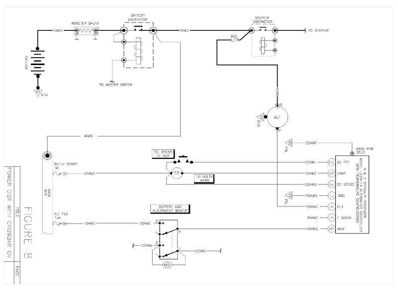
A schematic of how the LR3B would be incorporated into our system is illustrated in Figure 8.
I propose installation of a B&C Products LR3B-14 voltage regulator as a replacement for the factory system.