Phase III: Implement Improvements to Electrical Charging and Power Distribution Circuit
As pointed out in the section regarding grounds, basic improvements to any electrical system should include minimizing the number of joints and contacts in the system, and reducing the lengths of the wires used.
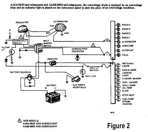
However, consider the Grumman Tiger's factory power distribution schema (Figure 2): power is delivered from the battery, through the battery contactor, through the ammeter, then to the main bus behind the panel. So far, this is not too bad of a system. However, take a look at the charging circuit: amperage from the alternator goes back through the main bus underneath the instrument panel back to the battery! This means that every bit of amperage that the alternator puts out must go through the main bus before going to the battery. Just imagine how far, and how many contacts, that encompasses.
Why is it, since the alternator sits not more than 2 feet from the battery, does the main charging circuit have to send up to 60 amps of power through longer cables, through the firewall, through the main bus, then back out through the firewall, and then to the battery, all of this wiring protected by a huge 60 amp breaker on the panel? Keeping in mind the goal of efficiency and minimization of connections, this certainly doesn't seem to work very well. The only possible reason that seems to make sense is that Tiger was not delivered with a shunted ammeter, therefore these cables must be run all that way, robbing efficiency and increasing the likelihood of failure.
To our advantage, Tiger N81140 has had an approved shunted ammeter installed. This presents us with an opportunity to greatly improve the system.
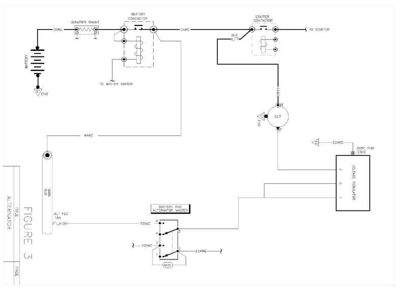
Consider Figure 3. Here we have removed the offending high-amperage circuit from the firewall, and connected the alternator "B-lead" to the battery side of the starter contactor. Note that charging energy now flows directly to the battery via the starter supply conductor. This shortens the large conductor that used to run from alternator B-lead to the main bus bar. The large starter cables can now serve two purposes: starting AND charging. This change also takes advantage of the battery's superior capability for reducing alternator noise on the system. Instead of conducting alternator noises to the battery by way of the bus bar, noises are shunted to the battery on shorter, fatter wires. The 2AWG wire is protected by an 80 amp in-line fuse placed as close to the starter contactor as possible; this allows us to remove the 60 amp alternator B-lead breaker from the instrument panel in the cockpit (and 6 feet or more of heavy gauge wire.)
There are those that would say removing this breaker from within the cockpit would remove the ability of the pilot to reset it if it pops in flight. However, consider the circumstances that would cause this failure: the only reason that this breaker would open is if the alternator fails hard or if there is a breach in the high-amperage wiring. In either case, the ability of the pilot to reset this breaker is a dubious one at best; it is best to leave it as-is while in flight and proceed with backup plans. Therefore there is, and never will be, any advantage to having that 60-amp breaker within reach of the pilot while operating the aircraft.
Wiring the aircraft this way is a big improvement. Alternator charging amperage does not go to, or through, the main bus or the master switch, radio noise is reduced, and charging efficiency is increased.
Ground Power Receptacle
Another desired modification, along with the rewired power distribution system above, is an improvement in the wiring circuit of the currently-installed Ground Power Receptacle.
Take another look at Figure 2. When external power is attached to the aircraft, it energizes the entire main power bus, bypassing the battery and battery contactor. Therefore, the pilot-in-command has no control over the distribution of power to his aircraft and relies upon the mercy and knowledge of the ground crew. In addition, there is no automatic overvoltage protection in the system. The Grumman Tiger has a 12-volt system; if 24 volts were accidentally attached to the power receptacle instead of 12 volts then this single careless act endangers the safety of the occupants of the aircraft, not to mention the risks of instantly destroying every electrical component in the airplane.
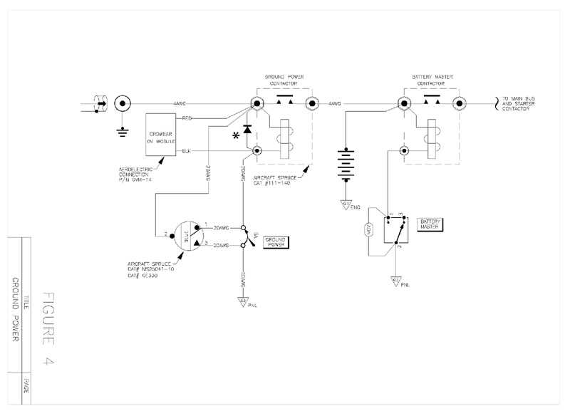
Figure 4 illustrates a significant improvement. Ground power is isolated by its own contactor, thereby giving the pilot total control of how external power is applied to the aircraft.
A separate switch with circuit breaker controls the ground power contactor, and the system adds a warning lamp to the annunicator panel to notify the pilot that ground power has been applied to the aircraft. In addition, automatic "crowbar" overvoltage protection is added, ensuring that any improper ground power added will be immediately isolated.
Once the pilot is satisfied that proper ground power has been applied to the external plug, switching on the ground power contactor connects external power to the battery only. At this point the system can be left alone if only battery charging is desired. Should the pilot decide to start the system on ground power, then the electrical system master switch can be closed and external power is applied to the entire system, allowing a normal start to be accomplished.
This system incorporates automatic overvoltage protection, notifies the pilot when the external plug is in use, and gives the pilot-in-command complete flexibility to decide how ground power is applied to the aircraft. In addition, any failure of any of the components in this auxiliary system does not affect safety of flight in any manner.