Phase II: Implement Improvements to Electrical Ground Circuit
Problems with poor conduction in high current paths (especially grounds) are most difficult to diagnose. Investigations into poor voltage regulation or starter performance always tend to begin with conductors other than grounds. However, it's important to remember that for every electron that leaves the battery another electron has to return via the other terminal; the same currents that flow in the power distribution wiring also flow in ground return wiring or conductors.
For example, consider the typical airplane where the battery is mounted in the engine compartment. Assume the battery is a pretty good lead-acid battery with an internal resistance of about 10 milliohms. Without welding it's difficult to make an electrical joint between any two conductors that's better than 1.0 milliohms per joint. Consider 2AWG wire with a resistance of 0.156 milliohms per foot. Total length of "fat" wires in the cranking path will be about 8 feet. Therefore 8x0.156=1.25 milliohms resistance in the wire alone. How about the battery and starter contactors (solenoids)? Well, two contactors in series held closed by an energized electromagnet. 4 joints at 1 milliohms each = 4 more milliohms. Total = 15.25 milliohms resistance in the starting circuit.
Now, this may not seem like much, but by applying Ohm's Law of V=IR (volts = amps time resistance), and considering that a starter may easily draw 200 amps, we see that we could lose 3050 millivolts, or 3.05 volts in resistance alone! If we start with a good battery of 12.5 volts, we see that we are only seeing 9.45 volts at the starter terminals; we've lost 1/4 of our cranking energy in just the trip from battery to motor!
Note that bolted joints make up a significant percentage of the total drop; even minimizing wire length has a relatively small effect compared to the reduction in number of bolted joints. With this in mind you can imagine how nasty things can get in a metal airframe where the engine is bonded to the engine mount by jumpers around the vibration isolators, the mount is "grounded" to the airframe through its mounting bolts, and the battery is bonded locally to the airframe.
Another consideration in aircraft grounding systems is called "Ground Loops." Ground Loops occur when two components of the same system are grounded in different parts of the airplane. Since wire can never have zero resistance, you end up with a small, yet significant potential between the two grounds. The results of these ground loops include degradation of voltage regulation; alternator "whine" or other noise in the audio system or radio; engine gauges that shift readings in response to changing electrical loads; and electrical noise in response to strobes, rotating beacons, flaps motors and other electrical motors.
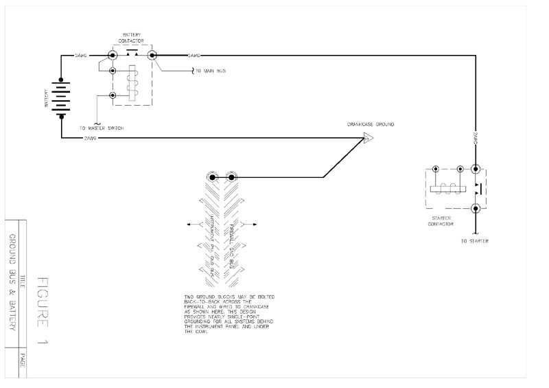
In Figure 1, labeled "Ground Bus & Battery", illustrates the most important ground wires in the airplane. The primary wire is from the negative side of the battery to the engine crankcase. The second wire is from the crankcase to a ground bus on the firewall and behind the instrument panel.
This grounding architecture optimizes engine-cranking performance and minimizes ground loop problems. Another positive side effect of this architecture is that under the original system, if the firewall-to-crankcase grounding were to become loose or break, the starter upon activation would try to find a ground through shields on the P-leads and the throttle and mixture cables. Grounding the battery directly to the crankcase eliminates this possibility.
Everything in the airplane will ground to one side or the other of this system. This single-point system of grounding will provide the most trouble-free, electrically-quiet, and highest-performing installation possible.
It is quite possible that many of the components of this system are already in place on the Tiger. The aircraft will have to be reviewed and further determination made as to the extent of work required.